|
62-67 CHEVY NOVA MUSTANG II Read and understand these instructions before starting any work!! SUPPORT VEHICLE WITH JACK-STAND, BEFORE DOING ANY WORK !! 1. Begin installation by jacking the car up and supporting it on sturdy jack stands. The stands must be located just behind the firewall on the flat side. Do not support the car from the front sub-frame. First, remove the hood and hood hinges. Remove the front wheels and disconnect the wiring to the front components such as the headlights, turn signals and parking lights, etc. Remove the front bumper and brackets, front fenders and grill. Be certain to retain all these bolts, as they will be reused when these parts are reinstalled. Next remove the core support and radiator. Next remove the engine and transmission. Now unbolt and remove the factory sub-frame with the inner fender panels. Next remove the old steering box and the steering column. The original steering column can be re-used with the new rack and pinion suspension with a little modification to the column. The original steering box will not be used. This is a good time to give the firewall a good cleaning and detailing, as there should be nothing more attached to it. 2. Start the installation of the new sub-frame by raising it up into place in front of the firewall. A floor-jack will help here. Line up the holes to the holes in the firewall and bolt it on using the new bolts and lock nuts. Tighten up the bolts. Next install the upper firewall support tubes from the front rails to the mounting surfaces on the firewall, using the original inner fender panel bolts. If there is a gap here, you can install some of the shims now, or bolt it tight and wait until the fenders are reinstalled. To determine the correct shims for the final sheet metal alignment. 3. Re-install the engine and transmission back into the vehicle. The weight of the engine will be helpful in compressing the springs while the installation of the suspension components. The factory engine mounts should line up to the stands on the sub-frame. Check the oil pan clearance, (rear sump oil pan must be used) 4. Continue with the suspension component installation. Install the upper and lower control arm. Place the coil springs up into the spring pockets and bring the lower arms up to them. Install the shocks by placing the first washer and rubber mount on the shock stud and sliding them up through the lower arms and shocks. Using a floor jack under the lower ball joint (if using a floor jack make sure lower control arm grease fitting will clear the floor jack cup) (Another option is to use an external spring compressor), compress the springs by raising the lower control arm up into position. The shocks are the “top-out” device and will hold the coil springs in place. As the lower control arm are raised, attach the upper rubber mount, washer and nut on top of the shocks when they come through the upper shock mount cups. Install the spindle assembly onto the lower ball joints and then install the upper ball joints into them. Now install the rack & pinion assembly using the two 5/8” in. bolts, washers and lock nuts supplied. Install the tie rod ends onto the rack and into the spindle arms. Estimate the alignment at this point. It is a good time to install the steering column and headers now, as it is easier to work on the steering column connection to the rack & pinion before the sheet panel is in place. 5. Finish up by installing the core support and radiator. Next install the grill & front fenders. You may have to adjust the shims at the upper mounts to align the front fender gap at the doors. Install the front wheels and place the car on the ground. The springs will need a little time to settle-out, before you get the proper ride height. The lower control arms should be level. If the car is too high, you may have to cut some off the springs. Cut only a quarter of a coil at a time & check the height again. Align the front suspension to the following specification: Caster 7/88 63/48 Camber 3/4861/28 Toe-In 1/8”61/8” with Manual steering: Caster-1.0 Camber-0 Toe-In - 1/16 with power steering: Caster- 4 Camber - 0 Toe-In - 1/16
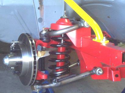 FIG.
2 FIG.
2
|
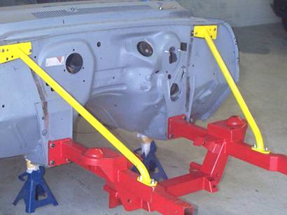 FIG.1
FIG.1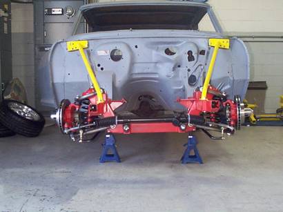 FIG.3
FIG.3
|
|||
|