|
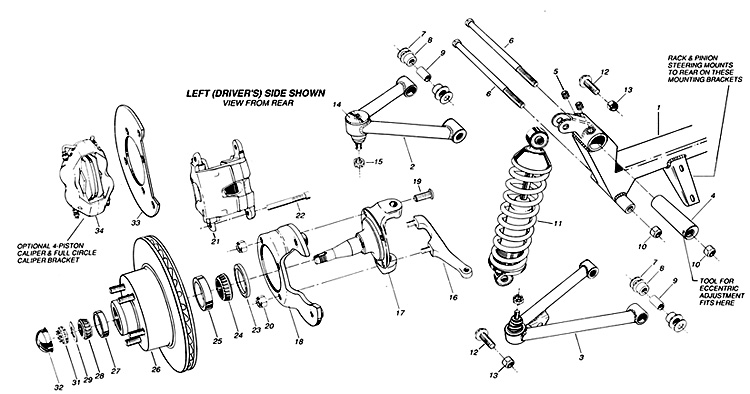
PARTS LIST
|
|
1
|
IFS Crossmember |
1
|
|
13
|
Coil-Over Mnting Lock
nut |
4
|
|
25
|
Inner Bearing Race -
installed |
2
|
|
2
|
Upper Control Arm -
Left |
2
|
|
14
|
Ball Joint - installed |
4
|
|
26
|
Brake Rotor |
2
|
|
3
|
Lower Control Arm |
2
|
|
15
|
Ball Joint Castle Nut |
4
|
|
27
|
Outer Bearing Race -
installed |
2
|
|
4
|
Eccentric |
2
|
|
16
|
Steering Arm - Left |
L&R
|
|
28
|
Outer Bearing -
installed |
2
|
|
5
|
Eccentric Lock
Set-Screw |
4
|
|
17
|
Spindle |
2
|
|
29
|
Spindle Washer |
2
|
|
6
|
Control Arm Mnting Bolt |
4
|
|
18
|
Standard Caliper Brkt -
Left |
L&R
|
|
30
|
Cotter Key - not
pictured |
2
|
|
7
|
Stainless Cup Washer |
16
|
|
19
|
Caliper Bracket Mnting
Bolt |
4
|
|
31
|
Spindle Nut with Lock |
2
|
|
8
|
Control Arm Bushing
Halt |
16
|
|
20
|
Caliper Bracket Lock
nut |
8
|
|
32
|
Grease Cap |
2
|
|
9
|
Bushing Sleeve |
8
|
|
21
|
Standard Caliper - Left |
L&R
|
|
|
Optional
|
|
|
10
|
Control Arm Mnting nut
|
4
|
|
22
|
Standard Caliper Mnting
Bolt |
4
|
|
33
|
Full-Circle Caliper Bracket |
L&R
|
|
11
|
Coil-Over Shock |
2
|
|
23
|
Grease Seal - installed |
2
|
|
34
|
4-Piston Caliper |
L&R
|
|
12
|
Coil-Over Mnting Bolt |
4
|
|
24
|
Inner Bearing -
installed |
2
|
|
|
|
|
|
Installation Notes:
|
The installation of T.
C. I's Independent front suspension unit may appear
complicated, but it is really very simple. Because
T. C.I. has engineered all the correct angles and
geometry into the crossmember itself, all that's
required are a few careful measurements to locate
the crossmember correctly on your chassis before
welding it into position. If you are installing the
IFS unit onto a stock frame, there is some work
involved in preparing the frame for the
installation, but the remainder of the job can be
accomplished with everyday hand tools. We recommend
that all welding be performed by a qualified welder.
We also recommend that you have the alignment
checked at a front end shop when you are finished.
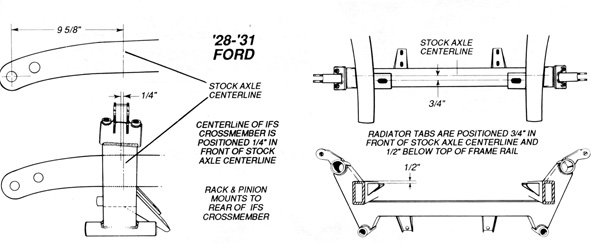
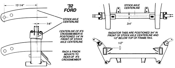
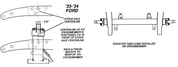
The installation
procedure is the same for all '28 thru '34 chassis,
but the location measurements differ. Please be sure
to use the correct dimensions from the diagram for
your particular car shown below.
|
| |
|
| 1. |
PREPARING THE STOCK
FRAME |
| |
· Remove all of the old
steering and suspension components. |
| |
· Tack weld two braces
to the top and bottom of the frame rails behind the
original crossmember to insure that frame rails do not
move. |
| |
· Remove original
crossmember by drilling out the rivets.
|
| |
· Box the frame rails
and weld up the rivet holes left by the original
crossmember. |
| |
· Finish grind all
welds. |
| 2. |
INSTALLING THE IFS
CROSSMEMBER & RADIATOR TABS |
| |
· Mark stock axle
centerline on the frame rails as per diagram at
right that applies to your chassis.
|
| |
· Fit IFS crossmember
squarely on rails, top and bottom, with the centerline
of the crossmember located 1/4" forward of the stock
axle centerline. |
| |
· Tack weld IFS
crossmember to boxed frame rails. |
| |
· Recheck all
measurements. (Check measurements diagonally to check
for squareness) |
| |
· Weld crossmember to
rails on all sides. |
| |
· Weld radiator tabs in
position as per diagrams. |
| 3. |
INDEPENDENT
SUSPENSION ASSEMBLY |
| |
· Install Lower Control
Arms onto crossmember. The lower arms are identical,
so there is not a left or right.
|
| |
· Install the Upper
Control Arms with the Eccentric onto the crossmember.
The upper arms are marked right and left as they are
different. |
| |
· Install the Spindle,
Brake Rotor assembly (assembly comes with bearings
packed and seals installed) to the ball joints with the
caliper brackets and steering arms facing the rear. |
| |
· Install the Rack &
Pinion steering gear. |
| |
· Install the Coil-over
Shocks. |
| 4. |
SETTING RIDE HEIGHT |
| |
· With full car weight
on suspension, Lower Control Arm pivot should be 1/2" to
1 " lower than the center of the Ball joint sleeve. To
adjust, jack up the car to remove the weight and then
turn the lower rings on the Coil-overs. The Lower
Control Arms will angle slightly uphill towards the
wheels when properly set. |
| 5. |
SETTING CAMBER |
| |
· Loosen set screw locks
on Eccentric housing.
|
| |
· Rotate Eccentric by
inserting the provided tool or an equivalent 114"
diameter object (phillips screwdriver) into the hole on
the side of the Eccentric. Rotating Eccentric is easier
with car jacked up, but Camber must be checked at ride
height. |
| |
· Camber should beset at
1/4" Positive. |
| 6. |
SETTING CASTER |
| |
· With set screw locks
still loose, Caster is set by sliding Eccentric
slightly fore or aft within it's housing. Gentle
tapping with a soft hammer may be required.
|
| |
· Set Caster between l"
and 1-1/2" Positive, making sure that both left and
right sides are set the same. |
| |
· Tighten set screws to
lock in Caster and Camber settings. |
| 7. |
SETTING TOE-IN |
| |
· Set Toe-in by
adjusting the tie rod ends on the Rack & Pinion steering
gear. |
| |
· Toe-in should be set
at 1/32" for radial tires and 1/16" to 1/8 " for
bias-ply tires. |