|
1. |
PREPARING THE FRAME |
|
|
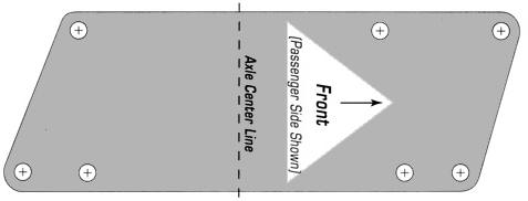
· Mark the original location
of the axle centerline on
the frame |
|
|
· Remove all of the old
suspension pieces by
unbolting the whole
crossmember along with the
control arms and spindles
attached. |
|
|
· Clean the frame of any
dirt and rust, especially
around the bolt holes where
the original front
crossmember bolts on and
where the spring mounts are
to be welded. |
|
2. |
INSTALLING THE
CROSSMEMBER |
|
|
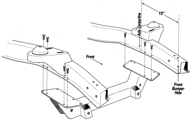
· Position the crossmember
under the frame. Align the
bolt holes on the
crossmember plate with the
bolt holes on the bottom of
the frame. NOTE: Make sure
that the center of the
crossmember is aligned with
the axle centerline. |
|
|
· Install the 14 nuts and
bolts to secure the
crossmember to the frame and
tighten. |
|
|
· Due to the variation in
frames, some holes needs to
be aligned or enlarged with
a 3/8" drill. |
|
|
· If you are using the Total
Cost Involved's tubular
lower control arms... |
|
|
a. Drill the lower
control arm holes in the
crossmember to 5/8". |
|
|
b. Position the longer
steel spacer on the rear
side of the crossmember
(using the lower control arm
mounting bolts through the
crossmember as an alignment
guide) with the reinforcing
gusset mounted horizontally
toward the engine. |
|
|
c. Tack weld the spacer
and gusset together and to
the crossmember. |
|
|
d. Double check all
clearances/measurements and
final weld. |
|
3. |
INSTALLING SPRING MOUNTS |
|
|
· Position the spring mounts
on the top, outside edges of
the frame rails, with its
centers directly over the
center of the lower
crossmember and axle
centerline. |
|
|
· The distance between the
middle of upper control arm
adjusting slots should be
around 29". Adjust the hats
in or out of the frame by
trimming or adding shim
where the hat meets the
sides of the frame. |
|
|
· To determine the left and
right sides, the spring
mounts should sit slightly
lower in the rear to
maintain the proper antidive
geometry. |
|
|
· Tack both spring mounts in
place, double check your
measurements (including
diagonally for squareness). |
|
|
· Mock up the upper control
arm, lower control arm and
the spindles, raise or lower
the spindles until the lower
control arm is horizontal to
the ground and check the
wheel camber. Make sure
there is enough adjustment
to set the spindle at O'
camber. |
|
|
· Final weld spring mounts
to the frame on both sides. |
|
4. |
COMPONENTS ASSEMBLY |
|
|
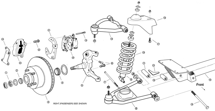
· Install the lower control
arms and strut rods, if
applicable, into the
crossmember. Install tubular
lower |
|
|
· control arms with the
Short Lower Arm Spacer (part
#13) position inside the
crossmember. The shock bolts
should face the rear of the
car. |
|
|
· Install the upper control
arms, with the serrated side
of the cross shaft facing
down, using the special
button head bolt, FORD
#385713-S-101. |
|
|
· Install the coil springs
and spindles, with the
steering arms toward the
front side. |
|
|
· Install brake rotors,
calipers and brackets, rack
& pinion steering unit, and
shock absorbers. |
|
5. |
SUSPENSION ALIGNMENT |
|
|
. Set ride height so the
lower control arms are
horizontal to the ground and
align the wheel with the
following specifications: |
|
|
Camber at 0º Caster at
1º Toe in at 1/16" |