|
|
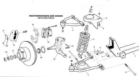
The
installation of Total Cost Involved's
Mustang independent front suspension
unit is really very simple because Total
Cost Involved has engineered all the
correct angles and geometries onto the
crossmember itself. All that is required
are a few careful measurements to locate
the crossmember and the spring mounts
correctly on your chassis before welding
them into position. Minor trimmings may
be necessary for some variations in the
frame.
We
recommend that all of the welding should
be done by a qualified welder using the
proper techniques. We also recommend
that the initial and subsequent wheel
alignment should be done by a qualified
alignment shop.
|
|
1.
|
PREPARING THE FRAME
|
|
|
·
Remove all of the old suspension and
steering components and mark the axle
centerline on frame.
|
|
|
· Tack
weld two braces in front of axle
centerline on too and bottom of frame
rails to prevent movement of frame
rails.
|
|
|
·
Remove the original crossmember by
drilling out the rivets.
|
|
|
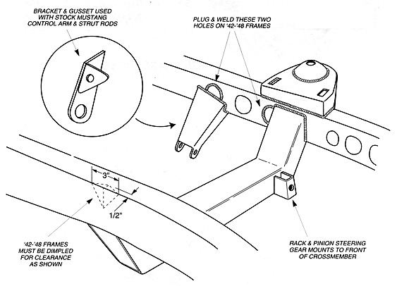
· On
'35-'40 frames, box the inside section
of frame; on '42-'48 frames, plug the 4
lightening holes with the weld in
circular plugs supplied as shown on
figure #4.
|
|
|
·
Finish grind all welds.
|
| 2. |
INSTALLING THE LOWER CROSSMEMBER
|
| |
· Fit
the lower crossmember squarely on the bottom
of the rails with the rack & pinion mount
facing to the front of car. The centerline
of the cross member should be inline with
the axle centerline. |
| |
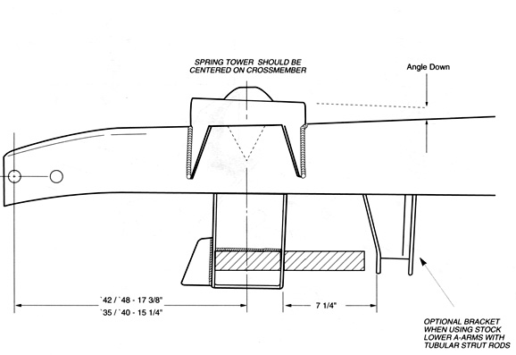
· Basic
location of axle centerline is given in
figure #3, check your wheel base to
determine your particular application. |
| |
· Tack
weld lower crossmember to frame rails. |
| |
· If
you are using the Total Cost Involved's
tubular lower control arms |
| |
A.
Drill the lower control arm holes in the
crossmember to 5/8". |
| |
B.
Position the longer steel spacer on the rear
side of the crossmember (using the lower
control arm mounting bolts through the
crossmember as an alignment guide) with the
reinforcing gusset mounted horizontally
toward the engine. |
| |
C.
Tack weld the spacer and gusset together and
to the crossmember. |
| |
·
Double check all measurements including
wheel base dimension and diagonally for
squareness. |
| |
· Final
weld the crossmember to frame on all sides
and final weld the steel spacers and
reinforcing gussets for tubular lower
control arm to the crossmember. |
| 3. |
|
| |
·
Position the spring mounts on the top,
outside edges of the frame rails, with its
centers directly over the center of the
lower crossmember and axle centerline. |
| |
· To
determine the left and right sides, the
spring mounts should sit slightly lower in
the back to maintain the proper antidive
geometry. |
| |
· On
'42-'48 frames, a slight dimple on the top,
outside edges of the frame should be made
before mounting the upper towers to clear
the stock Mustang coil spring as shown on
figure #4. |
| |
· This
dimple can be made by cutting a parting line
vertically on the sides and horizontally on
the top edges of the frame rails. Next step
is to tap the dimple inward, weld the
parting line, and grind the excess weld. |
| |
· Tack
both spring mounts in place, double check
your measurements (also diagonally for
squareness), and weld all around. |
| 4. |
INSTALLING STRUT ROD BRACKETS
|
| |
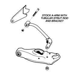
· If
you are using Total Cost Involved's tubular
strut rods, position the triangulated
bracket on the inside of the frame rails
with the open side facing down as shown on
figure #3 & 4. |
| |
·
Notice that there is a left side bracket and
a right side bracket for the tubular strut
rods. |
| |
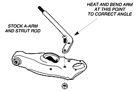
· If
you are using the stock Mustang strut rod,
minor bending of the strut rod is required
to correctly position the strut rod mount
under the frame. |
| |
A.
Mock up the stock Mustang lower control arms
with the strut rods and bushings into the
crossmember for alignment of strut rod
bracket. |
| |
B.
Position the flat brackets on the bottom of
the frame rails, angled toward the inside of
the frame with the triangular gusset mounted
toward the rear side of the frame as shown
on Figure #4. |
| |
C.
Heat the area around the bend (near the 2
mounting bolt holes) in the strut rod and
bend the strut rod so the flat mounting
bracket will line up to the bottom of the
frame rails as shown an figure #5. |
| |
· Tack
brackets in place and double check alignment
and interference. Final weld the bracket all
around. |
| 5. |
|
| |
·
Install the lower control arms and strut
rods, if applicable, into the crossmember.
Tubular control arms should be mounted with
the shock bolts toward the rear side. |
| |
·
Install the upper control arms, with the
serrated side of the cross shaft facing
down, using the special button head bolt,
FORD #385713-S-101. |
| |
·
Install the coil springs and spindles, with
the steering arms toward the front side. |
| |
·
Install brake rotors, calipers and brackets,
rack & pinion steering unit, and shock
absorbers. |
|
6.
|
SUSPENSION ALIGNMENT
|
| |
· Set
ride height so the lower control arms are
horizontal to the ground and align the wheel
with the following specifications: |
| |
Camber at 0º Caster at
1º Toe in at 1/16" |