67-69 TCI CHEVY
CAMARO FRONT CLIP
Read and understand these instructions before
starting any work
!! SUPPORT VEHICLE WITH JACK-STAND, BEFORE DOING ANY WORK!!
*APPLY ANTI-SEIZE COMPOUND TO THREADS TO AVOID SEIZING AND GALLING OF
THREADS
*APPLY THREAD LOCKING COMPOUND TO APPLICABLE FASTENER FROM VIBRATING
LOOSE
Do not paint or powder coat front clip till you check fit on the body
first, not all
Camaro bodies are exactly the same and if adjustments need to be made,
you will
want to do that before you do any painting or powder coating. This clip
is made to be installed without the factory rubber body bushings, it
bolts directly to the car without using any bushings. The original core
support bushings are the only bushings that will be reused.
1. Begin installation by jacking the car up and supporting it on sturdy
jack stands. The stands must be located just behind the firewall on the
flat side. Do not support the car from the front sub-frame. It is not
necessary to remove the front fenders, inner fenders and grill, this
clip should fit with very little if any clearance issues. Disconnect the
steering and transmission linkage and remove the radiator, engine and
transmission. The factory brake lines on the front will have to be
remade to fit your new clip and you should be able to reuse the rear
hard lines from the cowl back. Now unbolt and remove the factory
sub-frame making note to where the original sub-frame is mounted. The
original steering column will not work with the TCI front clip and an
ididit (67-69 Camaro application) column must be used. None of the
factory steering system will be reused. You will need to purchase two
universal steering joints and a steering shaft to hook your steering
back up. This is a good time to give the engine compartment a good
cleaning and detailing, as there should be nothing more attached to it.
Alignment Spec.
Manual Rack & Pinion: Caster +3 degrees ±.05degrees
Power Rack & Pinion: Caster +5degrees ±.05degrees
Camber -1/4degrees ±.05degrees
Toe-In +1/32”
 Photo 2a
 Photo 2b
 Photo 2c
 Photo 3a
 Photo 3b
Drill 3/8 hole (Photo 3b) through the firewall using the mounting bracket as a guide.
Make sure that all four of major mounting bolts are tight first.
. Then fasten it with the supplied 3/8-24 X1 Button Head Bolt (Photo 3c)
 Photo 3c
Next, drill (2 holes per side) through the
floorboard (Photo 3d) located between the firewall mounting point and
the rear-most mounting point using a 5/16” drill bit.
 Photo 3d
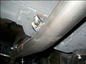 Photo 3e
Fasten by using a 5/16-24 x1 Button Head Bolts with head of the bolt
inside the car.
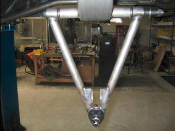 Photo 4a
4. Continue with the front suspension component installation. First, install the lower control a-arm shaft with Acorn nut towards the front of the car into lower A-arm and though the cross-member, the washers go on each side of the bushings. Complete assembly by tightening the 5/8” Full Nyloc Nut.(Photo 4a,b)
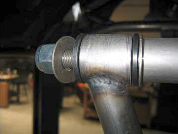 Photo 4b
Insert the control arm bolt from the front to the rear; place the supplied flat washer between each side of the polyurethane bushing.
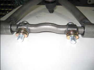 Photo 5a
Install the upper control arm into position using the supplied 9/16-18 x2 1/4” Button
Head Bolts. Space out the upper A-arm using the supplied 9/16” flat washers between
control arm and the clip. Use 3 flat washers on each bolt, this should be a good start to get to the alignment shop.
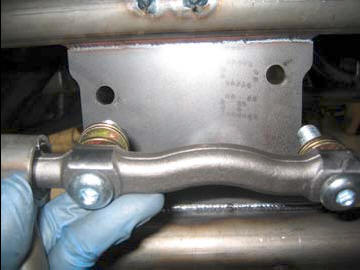 Photo 5b
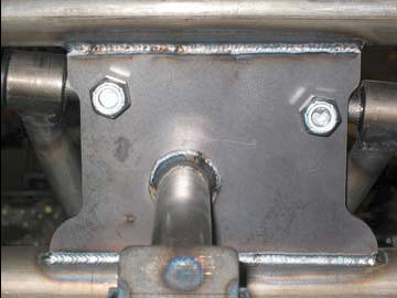 Photo 5c
Complete installation by tightening the supplied 9/16-18 Full Height Nyloc Nut.
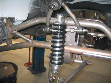 Photo 6a
Next, install the shock into position making sure that the adjustment dial is at the bottom and towards the rear of the vehicle. On the upper mounting point use the supplied
½ -20 x 13/4” Button Head Bolt and 1/2-20 Half Height Nyloc Nut and on the lower you will use the 33/4” shoulder bolt and spacer pointed towards front of the car. (Photo 6b)
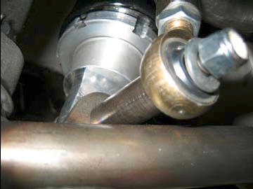 Photo 6b
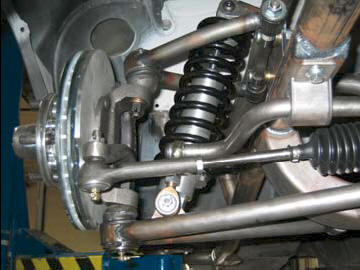 Photo 7a
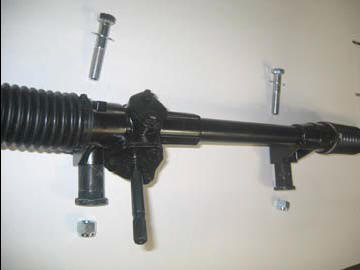 Photo 8a
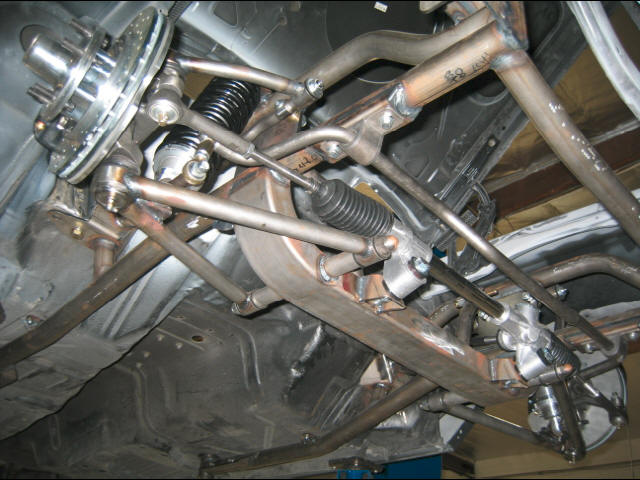
Next pre-assemble the rack and pinion (Photo 8a)
 Photo 8b
Install the rack & pinion assembly using the two 5/8” in. bolts, washers and lock nuts supplied. On power rack and pinions units the 5/8 thick spacer goes between the rack brackets on the cross member and the rack. Install the tie rod ends onto the rack and into the spindle steering arms. (Estimate the alignment at this point).
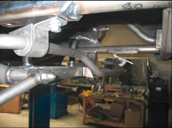 Photo 9a
Making sure that the step center section of the Anti-Roll Bar is down (to clear engine pulley)
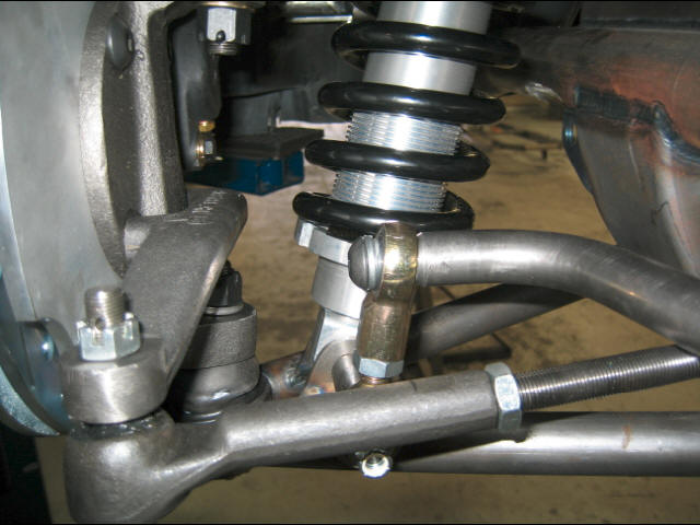 Photo 9b
Complete installation by fastening the
upper 1/2” Rod End from the lower shock mount bolt to the end of the
Anti-Roll Bar (Photo 9c) with supplied 1/2-20 x1 1/2” Button Head Bolt.
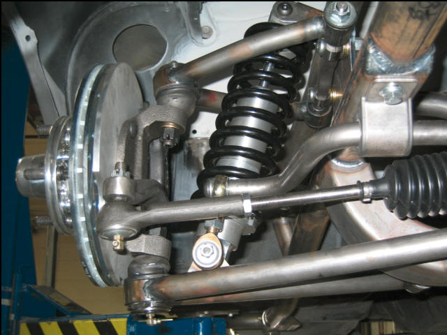 Photo 9c
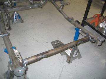 Photo 10a
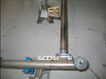 Photo 10b
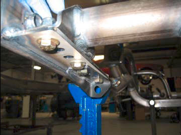 Photo 11a
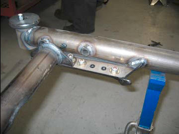 Photo 11b
P
 hoto 12
Fender Panel Cover
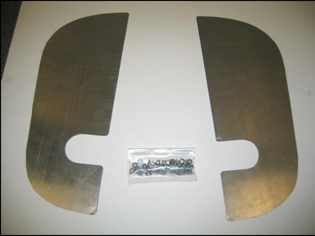
The stock inner fender does not have hole, clamp panels into position
fitting the notch over the upper shock mounts drill 7 holes that are
spaced evenly using a 3/16” drill bit. Fasten with the supplied 8/32
bolts nuts and washer.
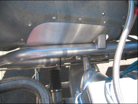 View from engine compartment
Passenger Side
View from engine compartment
Passenger Side
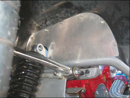 View from fender well Passenger Side