|
1965-70 Mustang Front Suspension Installation Instructions Thank you for choosing TCI’s Mustang front suspension package. The kit has been designed to not only allow your Mustang to handle corners, steer and brake better and have more engine compartment room but have that low sports car stance. Although the install will require cutting, grinding, drilling, welding and quite a few hours of your labor, the results are well worth the effort. I will take you through the install step by step. Before we get started lets show you some before and after pictures. |
|
|
|
|
|
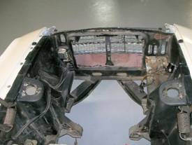
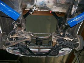
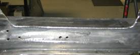
Before from the rear. |
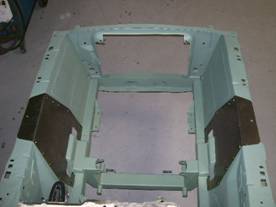
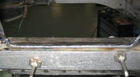
After from the rear. |
|
|
|
|
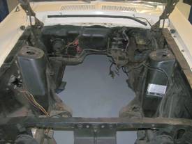
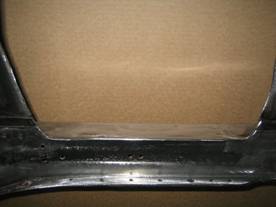
Before from the front. |
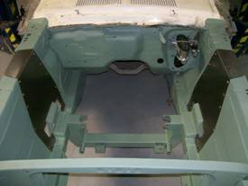
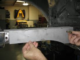
After from the front. |
|
|
Remove all the old suspension components including the steering column. |
|
|
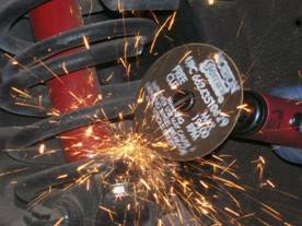
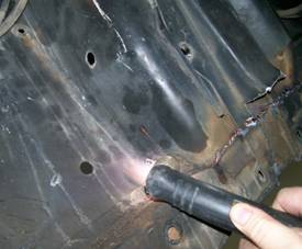
I used a die grinder with a cut off wheel to cut the coils in a couple of places for much easier removal. |
|
|
|
|
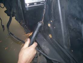
Next the shock towers, suspension brackets, have to be removed, but first clean as much of the underbody coating in the wheel well around the shock towers as possible to facilitate cutting. |
|
|
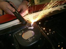
When it came to cutting off all the old suspension mounting brackets, I’ve tried a saber saw, a die grinder with a cutoff wheel, oxy/acetylene torch and a plasma cutter. By far the plasma cutter was the easiest, cleanest and most accurate. |
|
|
|
|
|
|
Start with the lower A-arm/motor mount brackets first.
When cutting, be careful not to cut into the main frame rail.
We will be grinding off the material welded to the main rail. |
|
|
|
|
|
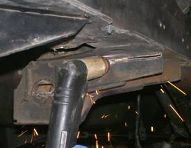
Next are the shock towers. The first cut will be made from inside the wheel well just above the main frame rail flange. |
|
|
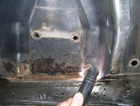
The rest of the cutting will be from inside the engine compartment.
Cut the lower edges of the tower from the frame rail. |
|
|
|
|
|
The vertical cuts on the towers are made at the bend radius between the tower and fender panel. |
|
|
|
|
|
The final cut is made across the top in the bend radius. |
|
|
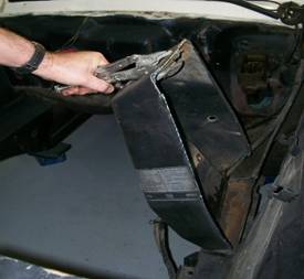
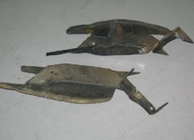
The shock tower completely removed. |
|
|
If a TCI sway bar package is being installed go ahead and cut off the stock sway bar brackets and the strut rod support channels.
This is highly recommended for superior handling and cleaner appearance. |
|
|
|
|
|
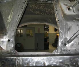
Remove all excess material, welds and paint from the main rails to all for the installation of the boxing plates.
Remove excess material around shock tower opening until it is flat to the fender panel; also straighten up inside cut lines for clean appearance. |
|
|
|
|
|
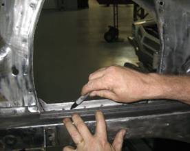
The outer flange on the top of the main rail has to be removed.
Draw a line through the centers of the spot welds.
|
|
|
|
|
|
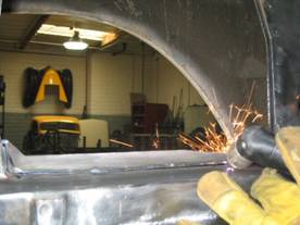
Carefully cut the flange off, leave about 1/8” or so extra material.
Use a grinder to remove the last 1/8” material.
If you try to plasma cut the entire flange off in one pass you will remove too much material from the frame rail. |
|
|
All the grinding is done.
Although you cannot see it in the picture, there is a split between the top and the side rail metal. |
|
|
|
|
|
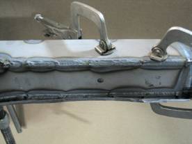
The top and outside of the rail will be seam welded back together.
Clamp a two foot flat piece of material (I used 1” x 2” aluminum bar) about 3/4” down from the top of the frame rail to maintain a straight edge.
|
|
Massage down any high spots or irregularities that aren’t straight and square with a small hammer.
Finally, weld the seam and side together also include the short flanges going up. |
|
|
|
Next grind the welded area flat and square.
At this point, you are done removing parts and preparing the frame rails.
This is a good point to do any other engine compartment cleaning you would like. |
|
|
|
|
|
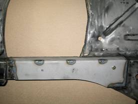
You are now ready to start installing the boxing plates to strengthen the frame in the cross member area.
The folded inside boxing plates are located by using a bolt and aligning the rear holes in the folded bracket with the upper front steering box hole (drivers side 7/16” x 3” bolt) and the upper idler arm hole (passenger side 3/8” x 3” bolt).
|
|
|
If the stock sway bar bracket was not removed, you will have to notch the inside flange one inch back for the locating holes to line up.
Check to make sure boxing plate sets totally flat all the way around on the stock frame rail. |
|
|
|
|
|
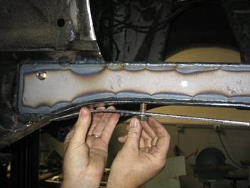
Install the correct outside boxing plate with the bolt and fasten with nut. (The plate with the hole closest to the rear is the passenger side.)
Align the boxing plate edge parallel with the top plate exposing an even section of the stock frame that when welded will tie both boxing plates to each other and to the frame. |
|
|
|
|
|
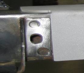
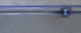
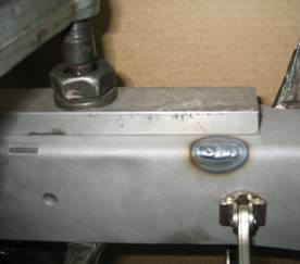
This is a close up of the parallel edges referenced above with a weld tack for reference. |
|
|
|
|
|
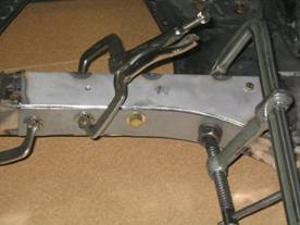
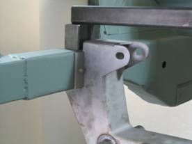
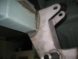
It is critical that the two edges are parallel even if you have to trim off of the bottom edge of the outside boxing plate.
This is because the 3/8 inch holes when drilled straight through after welding serve as a location origin for the cross member locating plate and the A-arm/shock tower (shown on left). |
|
|
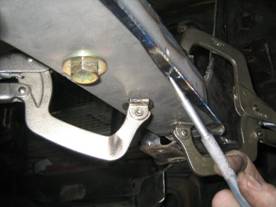
After clamping boxing plates using support plates double check to make sure plates are flat on the frame rail and as close to 90 degrees as possible to each other. |
|
|
|
|
|
It’s time to tack weld inner and outer boxing plates to each other and to the frame. When it comes to welding, I prefer to heli-arc because it’s cleaner and less grinding afterwards but a wire feed will work fine, just a little more clean-up grinding afterwards. |
|
|
|
|
|
The rosette welded three slots in the folded boxing plate tie it to the frame.
Note; the rosette weld to the left is not done yet. |
|
|
|
|
|
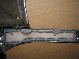
Weld the outside boxing plate totally 360 degrees around tying it to the frame and the inside boxing plate. |
|
|
Weld the inside boxing plate on the top, ends, sides and rosettes.
The portion following the bottom line of the frame will be welded later.
|
|
|
|
|
|
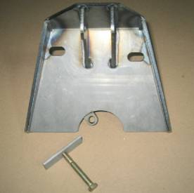
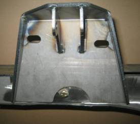
Install the formed bottom boxing plate using a 1/2”-13 x 1” bolt into the stock lower tube support bolt hole.
Install with the straight edge facing in and the curved and notched edge facing out.
|
|
|
|
|
|
Align inside edge of the bottom boxing plate even with the edge of the inside boxing plate.
Clamp securely checking for flatness. |
|
Tack-weld lower boxing plate. Weld inside edge to frame and inside boxing plate tying both together. Weld boxing plate on the underside of the frame. Don’t weld the out side edge at this time.
|
|
|
|
The outside edge of the frame is where the two stamped flanges of the frame are spot welded together and will require clearance grinding for the coil-over before welding.
|
|
|
|
|
|
The entire length of the stamped flange edges needs to be removed.
Using the outer edge of the lower boxing plate as the template, grind the two flanges till they match the profile of the boxing plate edge. |
|
Turn the heat up on your welder and seam weld both frame flanges and the boxing plate edge together. Remove the ½ inch bolt and weld up hole.
|
|
|
|
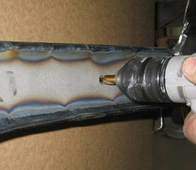
Drill the frame through from both sides in the 3/8” hole in the boxing plates to make the locating point.
Time to make it all look good.
Grind and sand the weld edges, round the corners and weld spot fill any pits or imperfections for a clean finish. |
|
|
|
|
|
You are now ready to start installing the cross member and shock towers.
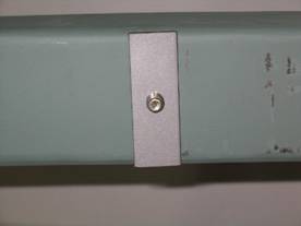
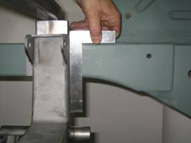
First install the one inch wide locating plate using a 3/8 inch bolt and nut through the 3/8 inch hole drilled in the boxing plates a few steps ago. |
|
|
|
|
|
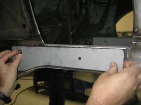
Next slide the cross member (steering rack brackets forward) between the rails behind (firewall side) the locating plates.
You may have to trim the ends slightly to get the cross member to tap in. Trim equally from both sides.
You want a tight fit so tap the cross member in with a soft mallet.
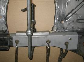
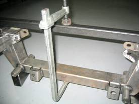
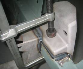
Use a sturdy flat cross bar (approximately 32” long), two short flat spacers (two inch’s) and a long c-clamp to pull the cross member up tight against the bottom of the frame and snug up against the locating plates. |
|
|
|
|
|
|
|
|
|
|
|
Next check to make sure that the cross member is 90 degrees to the top of the frame. This is critical for correct engine angle and lower A-arm angle.
Corrections can be made by slightly trimming the front or rear edge of the cross member that contacts the bottom of the frame. |
|
|
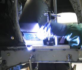
Double check for square and tack weld all sides and on the bottom.
Remove the locating plate and finishing welding all the way around, switching from side to side so as to not build up to much heat. Don’t weld up the inside 3/8 inch hole yet as it will be used to locate shock towers. |
|
|
|
|
|
The a-arm/shock tower bracket is mounted with the highest a-arm bolt slot forward and the lowest slot rearward.
This is the built in anti-dive feature.
Using a 3/8 inch bolt fasten the tower to the frame rail checking to make sure bracket sets flat against the boxing plate. |
|
|
|
|
|
Use a C-clamp from the inside and pull the bracket down snug to the top of the frame rail. When everything is tight, tack weld all the way around then finish weld. Next, remove the tab with the bolt hole in the shock clearance relief and finish weld. Weld up the four 3/8 inch locating holes and finish grind for a clean appearance. |
|
|
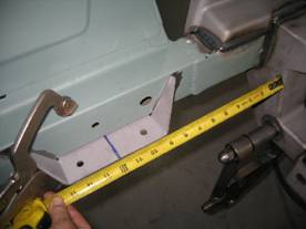
The sway bar bracket is mounted 12 inch’s from the front edge of the cross member to the center of the bracket.
Clamp securely to the bottom of the frame with the wings flush against the inside of the frame and weld. |
|
|
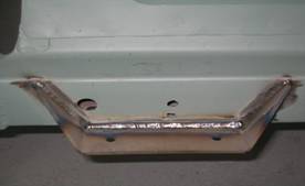
Completely welded. |
|
|
|
|
|
The lower a-arms are installed with the sway bar bung facing forward. The 5/8 inch shaft is installed with the acorn nut facing forward with a thin stainless washer on both sides of the urethane bushings on the a-arm. |
|
|
|
|
|
Install the a-arm onto the cross member and install the nylock nut using anti-seize on the threads and tighten. |
|
|
|
|
|
The shock assembly is installed next using the ½ inch bolts. |
|
|
When using Shock Waves with a spherical bearing, a provided spacer will be required on each side of the spherical bearing. |
|
|
|
|
|
Install the upper a-arm (both the same) with the shaft on the inside of the tower. Install the button head 9/16 bolts from the outside through the tower then the camber adjustment washers then through the a-arm and install the nylock nut with anti-seize on the threads and position the a-arm bolts in the center of the caster slots for a starting point and tighten the nut. Note: Start with 4 thick washers per bolt-drivers side and 2 thick washers per bolt passenger side, the driver’s side frame rail is wider than the passenger side. |
|
|
|
|
|
|
|
|
The spindle and brake assembly comes completely assembled with the bearing’s packed and seals installed and is installed next. With the steering arm forward and caliper rearward set the spindle onto the lower ball joint and install AN washer and nut, tighten and cotter pin. |
|
|
|
|
|
Install the top a-arm ball joint into the spindle. Install AN washer and nut. Tighten and cotter pin. |
|
|
|
|
|
The rack assembly needs to be centered to allow equal steering left to right. On a bench, turn the pinion out to lock one way. Measure from a convenient point to the end of the tie rod. (This rack was 17 ¾). Turn the pinion to the opposite lock position and measure from the same point to the end of the same tie rod (11 ¾). 17 ¾ minus 11 ¾ = 6. Divide by 2=3 Add that number to the smallest measurement (11 ¾” + 3” = 14 ¾”) and turn the pinion back till you get that measurement and your rack is centered. |
|
|
|
|
|
Install the rack using the two 5/8” bolts, washers and nylock nuts with anti-seize on the threads and tighten. |
|
|
Clamp a straight edge to each rotor as shown then using a tape measure front and rear; set the toe-in approximately 1/8” for a starting point. |
|
|
|
|
|
Install the tie rod end jam nut and then the tie rod end turning it an equal amount of turns per side until they line up with the steering arm tapered hole. Check the toe-in again, adjust if needed. |
|
|
|
|
|
Install the sway bar (center drop of bar down) next using the four 3/8” bolts, washers and nylock nuts. The spacer plate goes against the frame bracket first then the saddle bracket next. |
|
|
|
|
|
Before tightening, center bar equally both sides. |
|
|
|
|
|
Install the ½” rod ends as shown with the male end facing up. The sway bar rod end link needs to be straight up and down to allow adequate rack and pinion tie rod lock to lock clearance. Adjust by sliding the sway bar for and aft then tighten bracket bolts. |
|
|
|
|
|
I chose an Ididit brushed steel two inch diameter tilt retro fit steering column (TCI # 326-3100-00) and a Borgenson steering linkage package (TCI # 310-3120-03) to connect the rack and pinion to the steering wheel. |
|
|
|
|
|
The stock dash mount bracket was used with the 2 piece steel reducer that Ididit furnished. Note: The reducers kept sliding out as I was installing them so I tack welded the top shell to the top bracket and drilled an 1/8 inch hole in the bottom shell and bracket and pop-riveted the two together. |
|
|
|
|
|
I chose to fabricate a lower column mount that would fit the existing hole pattern and support the bottom of the column with two set screws on the inside for a simple clean look. TCI part # 000000000 |
|
|
|
|
|
With the column installed, put the Borgenson universal joints onto the end of the column and the pinion on the rack. The power rack and the column were both ¾”-36 spline X ¾” DD. |
|
|
|
|
|
Correctly measure as shown and cut shaft to length. When in doubt cut a little longer and trim to fit. Shaft must never extend past flush with the inside of the yoke this will cause an interference problem and system failure. |
|
|
|
|
|
The rack will have to be unbolted and slid forward to install the shaft. |
|
|
|
|
|
Loctite the set screws before tightening and loctite the jam nuts. |
|
|
|
|
|
To install the inner fender panels loosen the center fender bolts and remove the one over the shock tower. Position the correct panel over the a-arm and slide lip under the fender till the bolt holes line up on top and the three on each side of the panel with the existing stock inner panel holes. |
|
|
|
|
|
Install the 5/16 button head bolts in the existing holes and drill the lower two holes in each side of the panel. |
|
|
|
|
|
Install remaining bolts, tighten and finish by tightening the stock fender bolts. |
|
|
|
|
|
A 235-40 tire on an 18” rim was chose for adequate fender clearance. Correct ride height is with the lower a-arm level to the ground. Adjust the height with the threaded ring on the bottom of the coil-over. Castor 4-5 degrees positive with Power steering. Camber 0 degrees. Toe-in 1/8”. |
|
|
|
|
|
The spring on the coil-over is 350 lb. If you are using aluminum adjustable shocks adjust the damping knob all the way counter-clockwise (soft) and turn clockwise 3 clicks for a starting point. You are now ready to install the power train assemble. |
|
|
|