40-'46 Chevy Pickup

The first step will be to raise the vehicle and support it with jack stands all the way around. The vehicle should sit at the same angle as at ride height or slightly lower toward the front. Next, remove all of the original front spring shackle mounting brackets riveted in place are used as a reference point. Flatten the top side of the frame rail in the area where it is turned up for the old steering box mount. Now you need to modify the radiator supports crossmember. The front section of the crossmember remains in place to support the radiator while the rear section will need to be taken out for clearance of the rack and pinion unit. (see diagram A) The next step is boxing the front frame rail sections where the crossmember will be installed. Boxing plates have been supplied with your crossmember kit. Fit the plates up against the rear of the radiator crossmember. If the plates don’t lay against the inside edges of the frame rails you can grind the inside edges, but don’t grind off too much or the rails will be too thin to provide proper structural strength.

Installing the new crossmember is next. Measuring straight back 16 11/16” from center of the front spring shackle hole in the frame and making a vertical line on the side of the rail will show you the center line of the crossmember and the spindle. (see diagram B) Position the crossmember between the frame rail and slide it up all the way centered on the line you marked. If the fit is too tight you may grind the vertical edges that sit against the inside of the frame rail. When positioning the crossmember, the bottom of the must be parallel to the ground front to rear. Grind or shim as needed. Once you have made sure that the crossmember is fully seats against the underside of the frame rail, tack weld it into place.

The next step is installing the upper shock/spring towers. The towers sit on the upper side of the frame rail. Measure the towers sit fully against the frame rails. if you need to you can grind the towers to fit flush against the tops of the rails. When you have them positioned and fitting against the side of the rails, go ahead and tack weld the towers in place. (see diagram C)


*NOTE: We do not recommend using strut rods. Tubular control arms distribute brake load much better. If you choose to use strut rods, use the following instructions.

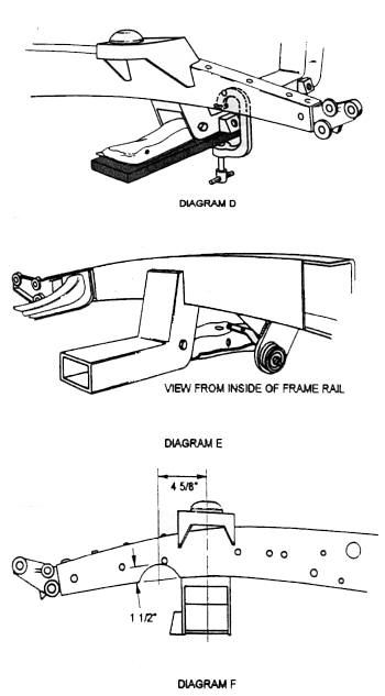
The strut rod plates and gussets are located using the lower control arms and the strut rods. With a piece of 2x4 lumber and a C-clamp install the control arm as shown in Diagram D. Install the strut rods onto the control arms. Assemble the large rubber bushings, cup washers and strut rod plates onto the strut rod ends. Align the tops of the plates with the underside of the frame rails. With the plates aligned, tighten the nuts on the strut rods to their fully seated position (see diagram E). 

The Pinto and Mustang strut rods are different lengths. It is recommended that you use the Pinto strut rods. The shorter Pinto rods will position the plates more closely to the bottom side of the frame rails. The Mustang rods are longer and will therefore need to be heated and bent out enough to align the strut rod plates to the bottom of the frame. Having the strut rods installed on the control arms allows them to be used as an alignment fixture so you can tack weld the plates in their proper location followed by the support gussets as shown in the diagram E.

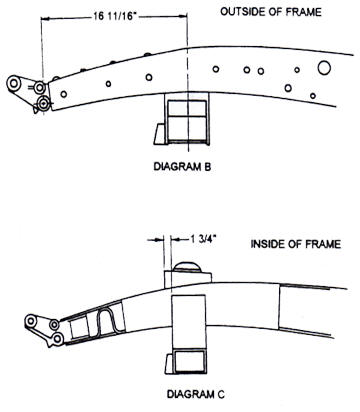
C-notching for the rack and pinion unit is the next step. Measure 4  5/8” forward from the centerline of the crossmember and up 1 ½”, make a mark. Draw a 2 1/8” radius using your mark as the top of the radius (see diagram F) Cut out the shape of the radius from the rail leaving about 1/8” of material to work with. Bolt the rack and pinion in place, check the clearance and the fit of the formed c-notch replacement piece. Finish grind the c-notch to fit this piece and then tack weld into place. Unbolt and remove the rack & pinion Unit.

Double check the crossmember, spring/shock tower, strut rod plate, gusset, and C-notch measurements. Once you are sure everything is where it’s supposed to be, finish weld all the way around each piece. MIG welding is recommended for this, but any well-done arc weld will be fine. Weld the crossmember and the spring/shock towers all around. The spring/shock towers and also be welded on the inside of the vertical gussets on the sides of the frame rail. Weld all around each of the pieces.

Now you are ready to complete the installation of the front suspension. The following are the recommended alignment measurements


  • Caster: 1  1/4 degrees + 1/4 degrees
  • Camber: 0 degrees
  • Toe-in: 1/6" for Radial Tires
  • Toe-in: 1/8" for Bias-ply Tires
Check the installation after a couple of hundred miles of regular use, including the alignment.  The new springs should have settled by this time so that the lower control arms now sit parallel to the ground. If the vehicle still sits to high you have the option of cutting up to one full coil off of the bottom of each of the springs. This should help to get the lower control arms to sit parallel to the ground like they should. If you have any questions, Please call us at 1-800-979-4278.
     

 |  Search |  Illustrated Installation Guides  |  E-mail Us |  800-979-4278  |


800-979-4278