|
These
instructions are used in several kit forms and may include more
information than you need for your kits installation. Please Keep
this in mind.
1. PREPARING THE FRAME:
-
Mark the
location of the axle centerline on the frame.
-
unbolt all
the old suspension and steering components.
-
Tack weld
two braces 4 forward of the axle center line to the top and
bottom of the frame. (this will keep the frame from moving when
the cross member is removed).
-
Remove the
original cross member by drilling out the attaching rivets.
-
Weld in
the boxing plates. Finish grind the welds.
2. INSTALLING THE LOWER CROSSMEMBER:
-
Fit the
crossmember squarely against the bottom of the frame with the
rack & pinion mounts on the front. The centerline of the
crossmember should be on the axle centerline.
-
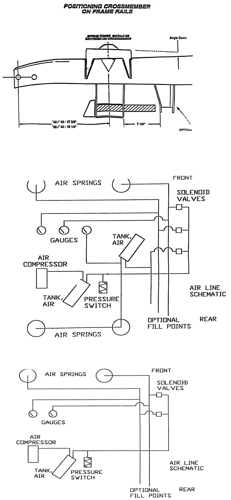
The basic
location of the crossmember is given in the figure. Check your
wheel Base to determine the correct location for your front
suspention.
-
Tack weld
the lower crossmember to the frame.
3. INSTALLING THE SPRING TOWERS:
-
Position
the spring towers on the top of the fame, centered on the axle
centerline. The towers should be outboard of the frame and
mounted such that they slope down to the rear of the vehicle.
(the angle of this slope should not be changed, as it controls
the amount of anti-dive).
-
Tack weld
the spring towers in place.
4. INSTALLING RETRO FIT KIT:
-
Locate the
bump stop against the outside of the frame and the back side of
the spring tower. The bottom of the bracket should be ½ below
the bottom of the frame.
-
Tack weld
the bracket to the frame. If you are using the bolt-on type,
then you can clamp them in place.
-
Locate the
upper shock mount 4 ½ behind the spring hat, and ½ below the
top of the frame and tack weld in place. If you are using the
bolt-on type, then you can clamp them in place.
5. CHECKING FOR ALIGNMENT:
(When
Performing this operation only tighten fasteners enough to contain
the parts and prevent them from moving, this way the same fasteners
may be used when you final assemble the parts to the required
torque)
·
Install the control arms with the acorn nut in the front and the
nylock nut in the rear. Dont tighten completely.
·
Screw in the 90 degree air fitting so that it faces away from the
center and install the upper spring adapter to the air spring using
the 3/8-16x1 bolts with the 7/16 head.
·
Install the air spring on the lower control arm with regular
3/8-16x1 bolts and washers. The slot in the spring adapter should
be pointing to the rear of the vehicle and the adapter should be
leaning away from the vehicle. If not swap sides with the adapters.
·
Slide the upper air spring adapter in the spring tower and fasten
with 7/16-20x3 bolts and cupped washers. The lower control arm has
slots to allow the air spring to be positioned so that the bottom of
the spring moves up and down directly below the top of the spring.
Adjust the spring as necessary using the slots.
·
Install the front shocks with 7/16-20x3.5 bolt, flat washers, and
nylock nut.
·
Install the upper control arm using the T bolts, flat washers, and
nylock nuts.
·
Attach the spindles
·
Install rack and pinion.
·
Raise the lower control arm until it is level. (this is the ideal
ride height)
·
Align the front Suspension.
·
Check that the bump stop hits the lower control arm about ½ before
the air spring reaches full bottom (the spring should be 3.3 inches
minimum at this point), and that the shock limits the extension of
the air spring before the air spring is fully extended (7.7
maximum). The air spring has 4.9 of travel, from 2.8 tall to 7.7
tall. The air spring has no internal device to limit the amount of
extension possible, and that a bump stop is used to limit the
compressed height of the air spring to prevent any damage to the
spring or vehicle.
·
If any components need to be moved. Move them and recheck the
location of the bump stop and shock absorber.
·
Unbolt the spindles, shocks, air springs, control arms, and rack &
pinion.
6. FINAL ASSEMBLY:
-
Final weld
all the components in place. For the bolt-on shock brackets and
bolt-on bump stops, use a transfer punch to mark the holes, then
drill them to 5/16. Be careful not to make the hole lager. Clean
the chips away. Do not install the brackets yet!
-
Remove the
two temporary cross member in front of the new crossmember.
-
The
chassis and suspension parts can now be painted and prepped for
final assembly.
-
Reattach
the air springs with anti-roll-over plates on the top and
bottom, control arms, shocks, spindles, and brackets. Make sure
to use thread locking compound where applicable. Fasten the
bolt-on brackets using the 3/8 self-tapping bolts and thread
locking compound such as loctite 271. Once the self-tapping
bolts are in, they are not to be removed!
-
Re-align
the front suspension and plum the air lines. When routing the
air lines, keep then away from high heat sources and anything
that might pinch or sever them. Once the air and electrical
plumbing is finished, check for leaks around the fittings using
soapy water. Once you have determined there are no leaks, youre
new suspension is ready to cruse!
|

